this post was submitted on 09 Apr 2025
47 points (98.0% liked)

Ask Electronics

3613 readers
1 users here now

For questions about component-level electronic circuits, tools and equipment.

Rules

1: Be nice.

2: Be on-topic (eg: Electronic, not electrical).

3: No commercial stuff, buying, selling or valuations.

4: Be safe.


founded 2 years ago
MODERATORS
 

I have an inspection scope camera that I'm attempting to repair. It's one with a camera on the end of a flexible rod to see into tight spaces. The pins that lead to the camera came out of the connector. I tried looking for teardowns or even replacement parts, but found nothing.

Two pins are still inserted, but I'm not confident they are in the right places. I want to get it working without the risk of frying everything. I've done my best to find where each pin goes, but there's not enough info for me figure it out on my own. The camera rod also includes an LED for light.

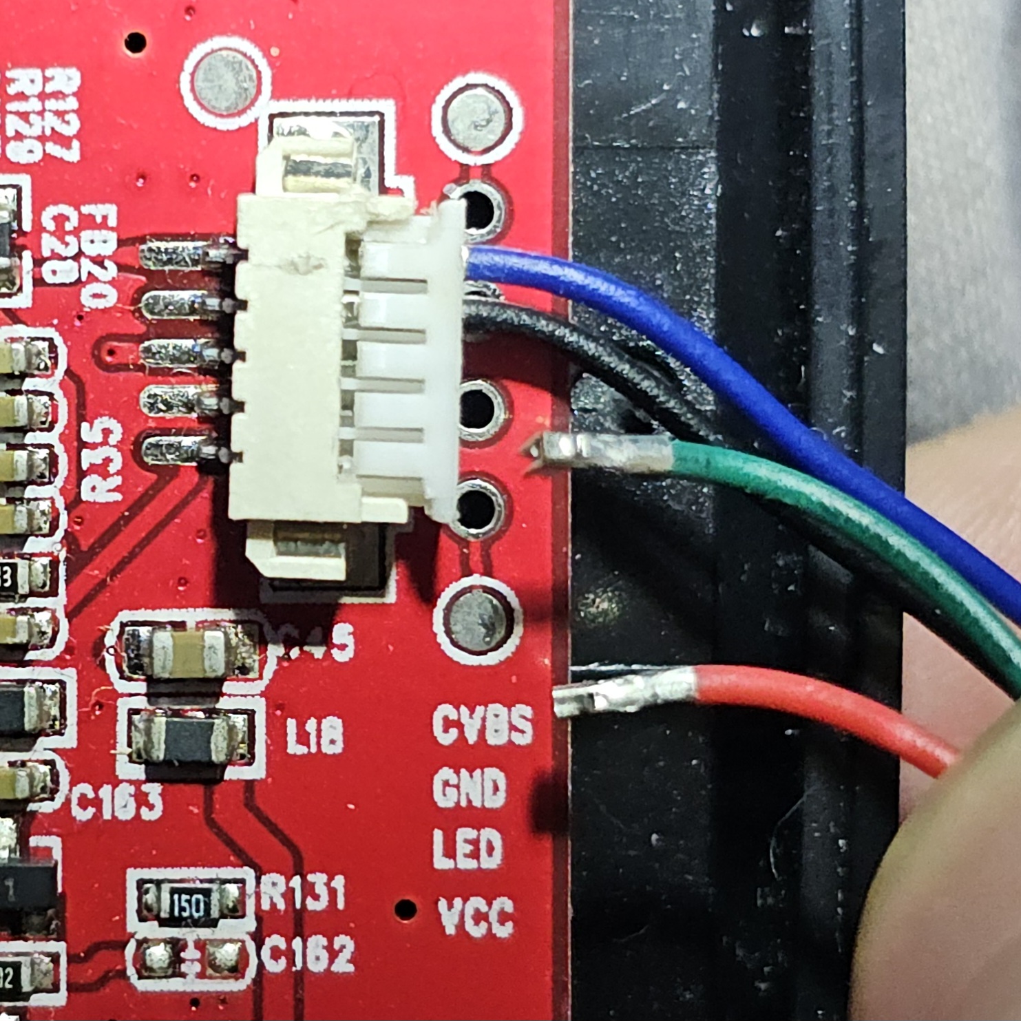
Here's a photo of the connector as it is:

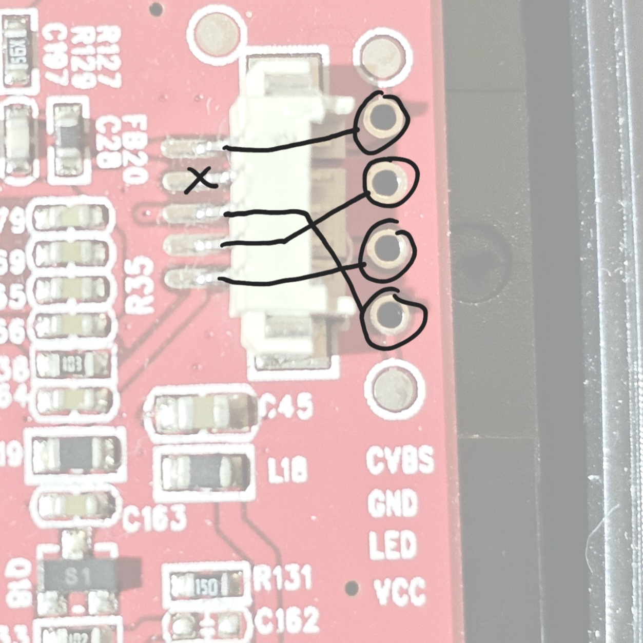
And here is the socket with it's pins labeled (the labels correspond to the testing pads and not to the socket pins):

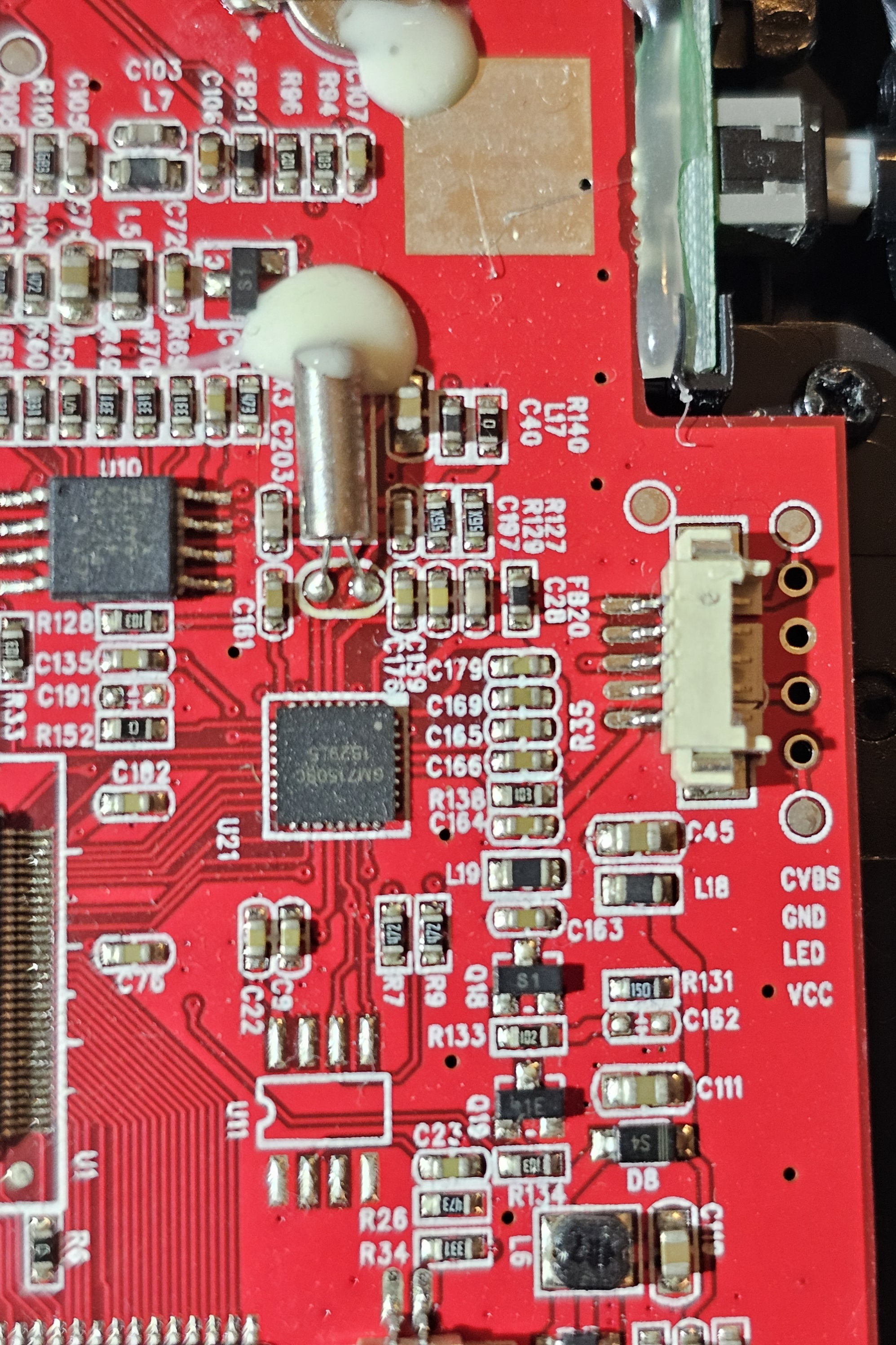
Here's a zoomed out pic if it's of any use:

I have a multimeter, so I can do any testing you can suggest. Unfortunately, I was not able to disassemble the camera to trace any wires.

all 15 comments
sorted by: hot top controversial new old
[–] [email protected] 5 points 3 days ago* (last edited 3 days ago) (1 children)

The second connector pin from the bottom is connected to what's almost certainly a ground pour, and this is in line with the through hole labels together with your diagram. This is your black wire.

I would bet money on the rest of the labels (and your diagram) being correct too, so red wire goes to middle connector pin.

If you're fairly certain that blue is in its correct location then we're done: green goes to bottom pin. If you are not, we can take a closer look.

From the top down, that would be

Blue
X
Red
Black
Green
[–] [email protected] 6 points 3 days ago (1 children)

Your order is correct!

With the help of the other comment suggesting to measure the voltage of VCC, I was able to verify all the pins were working.

[–] [email protected] 6 points 3 days ago
[–] [email protected] 4 points 3 days ago (2 children)

It looks as though this is a 5 pin connector, and you are saying that the second pin from the top is not connected but the black wire looks like it's in that spot. Black is often used for ground, is it possible that the second pin connects to ground instead of one of the through holes? It also looks like there are labels right below the holes that tell you what they are for. If I had to guess, black is ground and red is VCC. The other two are a bit of a mystery, but if you know that the blue wire goes up top then the green is probably the LED. This is all a guess, I don't actually know. So from the top it might be blue, black, green and then red. You could theoretically just clip the crimps off the wires and solder them in, it's the quickest and cheapest way. The more correctly way to fix it would be to identify the connector, and buy a crimping kit for that style connector. Common brands are Molex, Amphenol, and JST. It's probably a JST or a knock off, but they make a boatload of different products. Are there any numbers on either the socket or plug?

[–] [email protected] 1 points 3 days ago* (last edited 3 days ago)

I don't believe the pins in the cable are in the right places. I guess they were reinserted wrong when it was first opened up. Pin 2 is definitely a dead pin. I confirmed the ground pin to the battery connection.

[–] [email protected] 1 points 3 days ago

Also, if you can disconnect the plug and read what the voltage is on those holes that might also lead us in the right direction

[–] [email protected] 4 points 3 days ago* (last edited 3 days ago) (1 children)

Its a JST type connector I think. I bet if you check digikey (or whatever supplier you use), you'll be able to find kits for replacing the connector and its pins. Looks like the silkscreen labels on the right edge of the board below the connector show the pinout order.

Edit: on second thought, that labeled pinout may only be for the through-hole solder points. Safest bet would be to just identity the wires and solder them accordingly, rather than mess with the connector.

[–] [email protected] 1 points 3 days ago

The label is for the through holes, but I did confirm the corresponding pins for the plug with my multimeter.

[–] [email protected] 2 points 3 days ago (1 children)

unconventional approach:

use reverse image search in hope that some other guy on the internet published a picture of the same but with the wires still connected.

[–] [email protected] 1 points 3 days ago

Sadly didn't find any. Even looked at other camera scores in the similar budget range with the hopes that the camera part is reused on other devices. No luck. Not many teardowns of scope cameras.

[–] [email protected] 2 points 3 days ago (1 children)

Have you tried contacting the manufacturer directly? You might not get the whole diagrams but maybe they are willing to help you out. Worst they can say is no.

[–] [email protected] 1 points 3 days ago* (last edited 3 days ago)

It's a bit old and on the budget side. I'll keep that in mind as a last resort.