Maple Engineering

171 readers
1 users here now

Welcome to Maple Engineering

Visit Maple Engineer on YouTube.

This is a community for those who come up with creative ways to make maple syrup. You don't have to be designing and building homemade vacuum or RO systems to participate. Have you done something cool with your buckets and spiles? Tell us! Are you proud of your tubes and buckets? Show us! Have you built your own homemade gravity of pumped vacuum system? Show it off! Do you design, build, or install giant, gleaming, stainless steel maple syrup production systems? Tell us all about it! If you don't make maple syrup but love it on your pancakes of johnnycake and want to ask question, ask away. The people posting here love to talk about making and eating maple syrup.

You may also be interested in:

Maple_Syrup

RULES:

  1. All Lemmy.ca rules apply here.

  2. Everyone (see rule 98) is welcome.

  3. If you've seen a question 100 times answer it the 101st time or ignore it. Even better, write a complete, detailed answer and suggest that the mod(s) pin it to the community.

[Did you actually think there were 98 rules?]

  1. If you present something as fact and are asked to provide proof or a source provide proof or a source. Proof must be from a reliable source. If you fail to provide proof or a source your post or comment may be removed.

  2. Don't be a dick. Yes, this is a catch-all rule.

  3. The mod(s) have the final say.

founded 2 years ago
MODERATORS
1


When I decided to ramp up my maple syrup production my wife insisted that I come into compliance with the regulations for the handling of maple syrup which meant that my entire production path needed to be plastic, stainless steel, or ceramic. I had been using a Watts 350C brass pressure relief valve with my first homemade RO system.

This valve replaced the ball valve that I spent hours watching and feathering to try to maintain a steady back pressure in my RO elements.

Being able to simply dial in the back pressure that you want is AWESOME!

When I went looking for stainless steel valves I ended up putting out a call for offers on Alibaba. A really nice sales person named Grain contacted and after some back and forth recommended these valves. I have been SUPER happy with how the one I have been using has been working.

This year I'm moving away from four 400GPD elements to a single 2600 GPD element in a stainless steel 4040 housing. I'm planning to get the stainless steel nipples and fittings that I need to get it hooked up tomorrow in Ottawa. I need to remember to add Ts for a pressure gauge and a pressure transducer.

More pictures to follow.

2


I thought this was an interesting picture. It shows several years of tap holes, most scabbed over. You have to move your drill holes around so that the sapwood under the bark can heal fully.

3


This is the sled that I use on the maple syrup lines. I load it depending on what I'm doing. This is setup for spring cleanup and repairs. It includes a roll of 5/16 lateral line, a bucket containing fittings, tools, and a couple of colors of flagging tape, my Elk snowshoes, a can of 50:1 mized gas, a botttle of bar oil, and a Stihl MS160 chainsaw. I also have a Black and Decker 20V chainsaw that I bring out sometimes. When it's time to tap I will load up cordless drills, batteries, and 5/16" drill bits and a rubber mallet.

4


These are my 5/16" tubing insertion plyers. They have a pair of vice grips with a split, threaded rod adapter to grip the tubing and a pair of fingers to hold the fitting. I’ve modified them to make them line up a bit better for the way I use them. I’m thinking about taking off the plate with the fingers and making the slot smaller to better fit the fittings I use. This tool is an absolute must have if you’re going to build a vacuum tube system.

I bought these at CDL (catalog)but it doesn’t look like they sell this model any more. The closest one I see in the catalog is pn 6623157 which has an added knife for some reason.

5


One of the things I have to do in the late winter is look for animal damage to my lines. I suspect that this was done by a while tailed deer.

I had o cut out a section of the pipe and replace it. The roll of tube I'm working with this year is blue. I used a pair of flat hooks to make the splice.

6


I have begun the process of getting my system ready for the sugaring season.

First, a bit of explanation. I’ve been away from the hobby for three years. Two years ago the winter and spring weather were not good in our area. The season lasted for about a week. It takes me a solid two weeks to get setup and two weeks to tear down. A one week season doesn’t make it at all worthwhile.

Last year I was just finishing six months of chemo for Hodgkins Lymphoma and was too weak to tromp through the woods on snowshoes.

This year we’ve had a great winter (from a maple syrup perspective.) We’ve had LOTS of snow and lots of very cold temperatures.

So, I’ve been spending time in the woods freeing up my lines (many were down because of fallen trees and branches) and doing repairs. All but six of my lines are now up and ready to vacuum test. Two of the remaining six are up but in need of major repairs. Two are short and look ready to go. They will only need inspections. The other two are longer and have lines down. I will be working on getting those six up and ready to go this afternoon.

I quit yesterday late afternoon because I didn’t have any taps (spouts) in my tubing bucket. I have struggled to find my tools and fittings after three years. I had decided that I needed to make a trip up to CDL in Perth to buy taps and flat hooks. (I use the flat hooks to anchor the lateral lines to the wire supporting the main line to remove the stress on the saddle and to give me a loop that makes it really obvious if there is a leak on the lateral line.) This morning I decided to take another look and found a milk crate with a bag each of health Ts, end of line hooks, flat hooks, and taps.

Thank you past me for buying lots of supplies!

In this photo are a 5/16" MAXFlow end of line adapter (pn 66265099), a 5/16" MAXFlow Health T (pn 660300099), a 5/16" MAXFlow flat hook (pn 66303099), and a 5/16" MAXFlow spout (pn 66090516).

All parts are from CDL (catalog).

7
7
My working rig. (lemmy.world)
submitted 6 days ago* (last edited 6 days ago) by MapleEngineer@lemmy.world to c/maple_engineering@lemmy.ca


This is the sled that I use on the maple syrup lines. I load it depending on what I'm doing. This is setup for spring cleanup and repairs. It includes a roll of 5/16 lateral line, a bucket containing fittings, tools, and a couple of colors of flagging tape, my Elk snowshoes, a can of 50:1 mized gas, a botttle of bar oil, and a Stihl MS160 chainsaw. I also have a Black and Decker 20V chainsaw that I bring out sometimes. When it's time to tap I will load up cordless drills, batteries, and 5/16" drill bits and a rubber mallet.

8


My father's in his mid 70s and his hearing isn't very good in the frequency range that would be useful for finding his vacuum leaks.

I was thinking about setting him up with a directional microphone and a pitch-shifter app to bring environmental sounds down a couple octaves so he can hear them. There are tons of Android/iPhone apps that will pitch-shift in post, but none of the trial/freemium ones seem to work on a realtime monitor stream, especially on an external USB (UAC) microphone. I don't want to start buying dozens of apps just to try them.

Any app suggestions or other ideas for him?

9


My Purolator driver likes to deliver these McMaster-Carr boxes because he gets to look at the latest changes to my machine room (and to visit the caramel fridge in my office.)

This box includes a bunch of replacement O-rings for the John Guest fittings in my RO system. If you've ever tried to buy replacement O-rings you will have been frustrated by the fact that it's very difficult to figure out what kind of O-rings they are and that they are available in very small packages for a ridiculously high price.

They are EDPM Dash 110 O-rings (McMaster-Carr catalog number 9561K41 .) $1.71 for 25 pcs.

10


This is the setup I used to calibrate the vacuum sensor. The vacuum line connects on the right. The right T is the vacuum sensor. The left T is a vacuum gauge. The ball valve allows me to easily release the vacuum.

I use the vacuum transducers to monitor the vacuum level on the pump side and the collection (tree) side of the vacuum releaser.

11


This is the breadboard prototype of the first iteration of the industrial controller that I use to make maple syrup and that I call the SapMaster.

The Arduino Nano version ended up in a PVC project box from Turkey.

The Arduino boards is on the left in this photo.

12


Continued from Part 1.

image

Once we were happy with the setup Lulu started welding. Here she's welding the cross bars into place.

image

We've taken a bit of a leap forward at this point. The floor of the fire box is welded in, we've installed the back of the fire box, and the cross bars for the rear baffle are welded into place.

In the next version of this evaporator I plan to bring an air feed in under the baffle at the back so that I can push air in under the first grate. This rear wall of the fire box is solid.

image

In this photo we've added the framing for the fire bricks on the back wall of the fire box and are test fitting couple of fire bricks, one at each end.

image

We used a big piece of cardboard to make a template for the left half of the rear baffle. The oil tank has lots of indents and curves to work around.

image

We traced the cardboard template onto a piece of steel sheet and cut it out. The fit wasn't bad but there was going to be some gap filling to do.

I think that in retrospect I would have used treaded rod and a turnbuckle to close some of this gap for welding. I'll do that next time and take pictures.

image

We made the sides of the baffles out of multiple pieces of sheet because that's what we could cut out of the other tank. We used the same process here, drilling holes so that we could weld the sheet to the cross bars.

image

There was lots of welding and lots of grinding to do to get the rear baffle installed but we got it done.

image

These two cross bars behind the top frame cross bar we saw earlier will support the chimney connector. Note the circular cutouts for the chimney ring.

image

The hole in the rear deck lines up with the circular cutouts in the cross bars.

image

The chimney ring sits above the hole on the rear deck and we welded everything together.

image

We careful when you're using zip cut disks. They have no respect for work gloves or fingers.

image

I spent too much time producing this paper template for the point where the leg meets the tank. We wrapped the paper around the tube, clamped the tube in place, then scribed the connection with a block of wood and a Sharpie. I then spent time working with scissors to improve the fit.

Next time I do this I will build the jig that you see in the next photo and scribe the connection with the leg clamped in the jig.

image

This large rectangular jig sits on the tank and holds the legs in place for welding. We were able to tap the jig to adjust it to make sure that it was level in relation to the tank and that the legs were therefore plumb.

image

We marked the tank and did some weld prep.

image

Next, we tacked the legs and the long axis gussets. The legs on the old evaporator were flimsy. These ones would not be.

image

We then removed the jig, used carboard to design and cut the short axis gussets, tacked them in place, and welded the leg and gussets.

image

Now we could finally get it up on its feet. This is, I believe, the greatest improvement over the old evaporator. Using the screw type scaffold jack feet allows me to level the evaporator on uneven ground or an uneven floor. Even in my new sugar shack the ground moves a bit in the spring. Being able to kick the handles and bring it back into level easily is amazing. I had to shorten the legs a bit but that was easily done with a cutting disk on the grinder as they were hollow. Solid ones would be harder to cut but the hollow ones work fine for this application.

You can see in this photo that we have started to tack together the fire grate. It's made of 1 1/2" x 1/4" bar and 2" x 2" x 1/4" angle.

image

A closer look at the tacked grate.

In the next version I will weld bar onto the open side of the angle to add additional strength. With differential heading from the fire the grate warped.

image

The door is a frame of 1" x 1/2" steel channel with a field of steel sheet. The hinges are trimmed down and welded to the door frame and the frame of the door.

image

I glued wood stove gasket into the channel frame on the door to keep the smoke in. The chimney drafts enough air that smoke doesn't home out the vent holes.

image

We built the door handle and closure out of some scraps of steel that I had in my scrap bucket.

This was a great build and Lulu and I had a lot of fun. There are LOTS more photos that I didn't include here. If you're interested in any specific aspect of this build or have any questions please feel free to ask or comment.

13


This is going to be a long post. I will likely have to break it up into parts. So this is Part 1.

In the late winter of 2019 my hand, Lulu, and I built a new oil tank evaporator.

(You can click on the images to see higher resolution versions.)

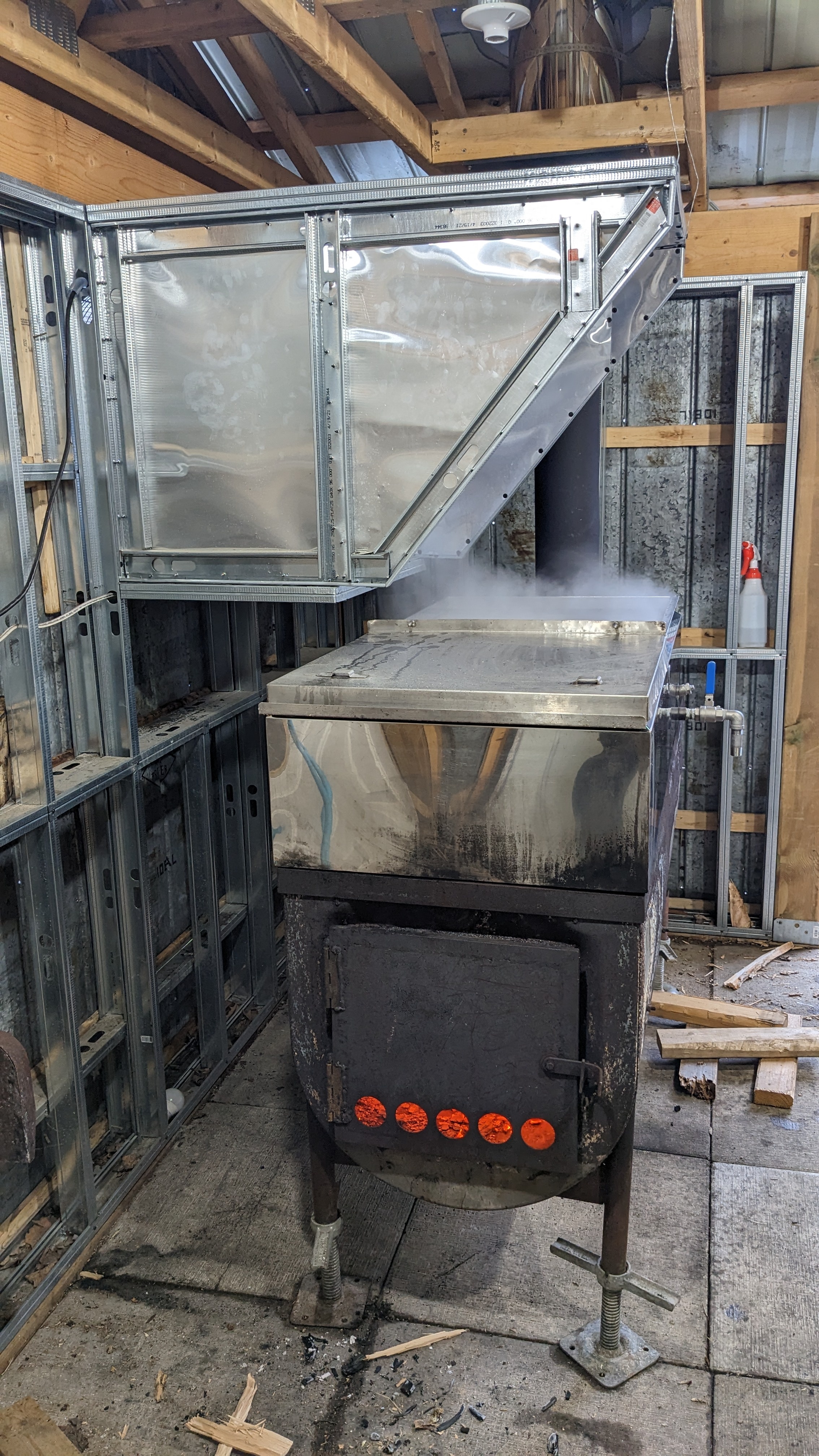
This is my original evaporator. My wife bought it from a local guy about four years before. It worked ok but I wanted to make improvements.

image

Note that the door doesn't fit well and the legs are the original oil tank legs which are intended to sit on a concrete floor and not be moved. The body of the evaporator is completely open so I had to pile concrete blocks and piece of steel in there to deflect the heat toward the bottom of the pan.

image

The pan was steel, folded and soldered and it leaked and was hard to get clean. The hardware was mostly brass and was tenuously connected to the pan.

image

Lulu (L) and I (R) set out to make improvements.

image

This is the oil tank that will become the body of our evaporator (and later the body of the evaporator and replaced and improved on this one.

PLEASE NOTE: Cutting an oil tank or any container which has contained flammable liquid will KILL YOU. This is NOT something that you should try unless you know exactly what you're doing. Seriously, it will explode and it will fuck you up.

image

We used welding magnets and aluminum angle to draw a line around the middle of the tank. I think cut the tank in half. (Read the warning above. I'm not going to tell you how I did this. If you don't know how to do it safely get help or ask someone who does know how to do it safely to do it for you.)

image

It was getting late when we finished cutting the tank in half so this photo is a bit dark.

image

We built a frame out of 2" x 2" x 1/8" steel angle. Here we have the long sides clamped to the top of the tank, squeezing the sides straight so that we can measure the length of the required short pieces. The sides of the tank bow out once it is cut in half. You don't want to squeeze it so hard that the side bows in. Just look at where the angle hits the tank and make sure that it's touching the tank along it's full length.

image

We cut the long and short pieces on the dry cut saw then prepared the corners. We used right angle welding corner clamps to hold them in alignment while we welded them.

image

Once the corners were welded we did some grinding. So much grinding. When you're an amateur welder the angle grinder is your friend. My hand had never welded before coming to stay with us so she did a lot of learning on this project. I let her do a lot of the welding then came along behind her and did some grinding and touch ups where necessary.

image

We laid out for, measured, and cut a 2" x 1/2" flat bar door frame.

image

Next, we cut and welded on the first of three cross bars in the top frame. This one is upside down compared to the other two. This one is the back edge of the pan. Behind it is the read deck where the chimney connector will be.

image

This little Cub Cadet/Yanmar tractor acted as our welding table for the project. Here you can see the top frame with the rear cross bar. Note also the interrupted weld around the outside bottom of the top frame. The inside of the top frame is continuously welded.

We didn't install the other two cross bars at this point because they would have been in our way as we did the interior welding.

image

We marked and cut the door opening in the end of the tank.

image

Then we welded in the door frame. The welds are ugly but we're amateurs.

image

In this photo we're working on how we're going to attach the half fire bricks to the evaporator. We decided on some 1 1/2" x 1 1/2" x 1/8" angle at the top and bottom with two pieces of the same angle welded back to back with 1/4"-20 studs to attach it to the wall to retain the bricks where they meet.

image

This was the retainer bar that we built. We slipped the fire bricks into the upper and lower angles then slipped this bar in between the two courses of bricks and bolted it to the side the tank.

image

In this photo we're doing a fit up to see where the holes need to be drilled for the retaining bar and where the lower angle needs to be welded on.

image

In this photo we have the lower angle welded in and are just testing to see how the whole setup works. It works well.

image

Next, we started to build the back and bottom frames of the fire box. The plan was to build a baffle at the back of the first box to direct the heat up and a baffle across the back of the tank to hold the heat against the bottom of the pan.

image

We cut these three pieces of angle to set the floor even with the bottom of the door to make it easy to drag out the coals and ashes when the boil was done.

This is one of the things that I am going to fix in the next evaporator build. I should have set the floor down the thickness of a half fire brick so that the floor of the evaporator was protected. The heat of the fire built directly on the floor of the fire box caused it to warp.

image

Most of the flat steel you see in this build came from another oil tank that we cut up as we needed pieces.

Please reread the warning about cutting oil tanks at the beginning of this post.

image

Here you can see the piece we cut out of the tank above to use as the floor of the first box. We did some cutting and grinding to get a decent fit.

image

We drilled a series of holes to line up with the middles of the cross bars so we could weld the sheet onto the cross bars.

image

Everything was dry fit together so that we could make adjustments before we started welding. We ground back the plate a bit at the ends of the cross bars so we could wend the cross bars to the tank well.

Continued in Part 2.

14


YouTube Video Full System Tour of my Machine Room

This is a video that I made this spring to explain what's in my machine room and what it does as well as the supporting development and operations hardware in my office.

15


Like most of the things I build this was put together from parts I bought on Ebay, at Lowe's and my local Home Hardware. It used 100 GPD membranes and a small booster pump. It chugged away but we quickly outgrew it.

16


I built this releaser from PVC pipe that I bought at Lowe's in Ogdensburg, NY, check valves and solenoids that I bought on Ebay, and fence T-bars that I bought at TSC. The controller was an Arduino Nano in the grey box on the side of the releaser. This one was vertical and sat on top of the IBC draining into the port on the top. It worked quite well and didn't cost a lot to build. I can't remember how much it released per dump but it was under 4 L.

17


In 2020 I a hand and I built this insulated box so hold the vacuum pump, RO pumps, vacuum releaser, and RO. This prevented them from freezing overnight and eliminated the necessity to carry them in every night and back out every morning. The vacuum releaser is the two white circles on the right. The little heater bottom right stayed on overnight.

The only problem with this system was that my main storage, a 1,000 L IBC, was outside and the plumbing and valves froze up. It was a big improvement but it left a lot of room for improvement.

18
2
submitted 2 years ago* (last edited 2 years ago) by MapleEngineer@lemmy.ca to c/maple_engineering@lemmy.ca


This is the machine that runs my maple syrup machine room. The PLC (the large grey box on the left in the second section from the top) runs a MEGA2560 Pro Mini with an ESP32 as a WiFi modem. There are more than 4,000 lines of BascomAVR running on the MEGA2560 and around 800 lines of Sketch on the ESP32.

The top section is power distribution. The middle section is supposed to be PLC only but my 24V power supply and distribution leaked into the right hand end opposite the PLC. The bottom three sections from left to right are analog input, digital input, and digital output.

This thing runs a vacuum pump (a MasterCool 90066A), a transfer pump (a small Iwaki), an RO pump, and two solenoid valves (to be replaced with motorized ball valves this summer.) It takes inputs from a bunch of float switches, two vacuum transducers, a pressure transducer, three high precision digital thermometers, and two last time of flight sensors. This thing runs the entire process from the trees through collection and storage through the RO into secondary storage and out a tap to be boiled in the evaporator.

The PLC uses a pair of custom boards that I designed to fit in the BUD case they're installed in. I'll post pictures of the inside shortly.