Ask Electronics

3613 readers
1 users here now

For questions about component-level electronic circuits, tools and equipment.

Rules

1: Be nice.

2: Be on-topic (eg: Electronic, not electrical).

3: No commercial stuff, buying, selling or valuations.

4: Be safe.


founded 2 years ago
MODERATORS
51
1
submitted 8 months ago* (last edited 8 months ago) by [email protected] to c/[email protected]


I built a Ploopy mouse yesterday. All the buttons work, and for the most part it's fine. But the movement is on and off laggy. Sometimes it works great, even faster than what I had before, and then it just stalls or stutters and slows down for a several seconds. I've tried a couple different USB cables, I've taken it apart and tried to reseat everything, I took the optic piece off and tried to blow out any dust that may have been in there. But it's still on and off laggy. Happens in windows and Linux both.

This is only the second thing I've ever soldered, and I'm sure I did a pretty trash job of it. The board is mostly done but you have to solder the optical chip in at build time. Could that cause it to be laggy like that? I don't see any pins accidentally soldered together, there's separation between each soldered lead, though I definitely can't do the nice pretty little dots, they're ugly as hell.

They've provided instructions to build/update the firmware, could that help maybe?

Just wondering if there's any other ideas to help fix this? If I knew it was a legit bad board or something I could maybe go back to the seller and see about getting a replacement, but I'm afraid my soldering could be at fault in which case I don't want to make that his problem. So I'm hoping someone here may have an idea. I love the idea of this diy 3d printed mouse, just hoping it wasn't a $100 mistake.

Thanks in advance.

52


I have a foldable 120w one with 4 panels in sewn cloth. Gust blew it and the little plastic anti-tug box broke so wires could move.

Still worked, but one day the watts were halved.

Examined wires closely, not easy because most of that little protective box still in place, but it looked like they twisted around each other in there, so I untwisted and glued anti-tug fitting to case so it can't turn again.

Today broke two mounts of the little box so I can see wires clearly, two stranded leads with what looks like a can cap in between and the remains of a foam strip that looks like it went in between.

Still puts out half wattage at about 24v, but I'm wondering if wires under the fabric case are disconnected. It used to put out more than the rated 120w, I've seen 138w on the battery boxes meter.

My thinking is either open the case seam to see in, or assume a panel or two shorted and are lost anyway, leave alone and be happy it works at all.

One thing I don't know what happens when solar panels short, if that's what happened. I do have a DVM and could check resistance, but without disassembly it would be cumulative.

Or the twisting could have disconnected one or more panels, they're supposedly wired in series and its putting out like it would on an overcast day. In which case I might be able to reconnect them.

Bluetti is nice enough superficially but I'm sure I'm unlikely to get tech info out of them. They're very Apple-like is dealing with consumers.

(BTW, they will sell your email address to multiple marketers promoting "sales" of bluetti products after a purchase. Not a lot, but the sender addresses are always different.)

53


Kind of an ELI5, but I tune a radion into a specific frequency to listen to a station. If that frequency is constantly being modulated (changed), how is the radio not going in and out of tune? I expect it is finding a way to measure multiple frequencies around the tuned station and decodes the data from it's deviation from the tuned frequency?

54
1
submitted 9 months ago* (last edited 9 months ago) by [email protected] to c/[email protected]


Hello,

I am looking for a good way to mount a daughter board to a motherboard that can be ~~hot~~ swappable. I would like it to be able to mount securely preferably with mechanical clips or fixings.

There will be up to 10A to go through it for power as well as around 10 signal pins. Obviously I can use several pins to get the required current rating.

I have seen DIN 41612 connectors but I am concerned about the daughter board coming loose.

If anyone can help me it would be much appreciated 😊

55


I've got a VFD display on board along with UPD16311 driver is made for negative voltage around -30V and i think so is display (i couldn't find any info on display) and I'm doing it mostly from junk parts. I want to know what devices could/should contain power supply for such voltage. I've tried -12V from psu i've got lying around but it didn't work. There's also a chance that display itself is damaged but there's no visual sign of it.

56


According to the A4998 datasheet you're supposed to wait 1 millisecond after waking from sleep to allow the circuit to energise.

What is the worst that can happen if you neglect to do this? I use stepper motors to drive a plant watering pump and losing a step or two really isn't an issue. Is there a risk of damaging the module or is losing the first step the biggest risk?

I trigger the pump by pulling the EN pin low and a 555 timer on the STEP pin makes it pump continuously. It seems sensible to pull the SLP pin down as well with it as that saves a little bit of power.

57


I have a 3d printer in my car powered by a bluetti eb3a. The bluetti is charged by the 12v outlet in my car while driving. I have a 24v solar panel i want to mount to the roof of the car. My bluetti has only one dc 7909 input. So got a a Y splitter to combine power from the car and panel. But when plug it into the car outlet that turns off when i turn off the car, the solar panel turns on the stereo. Thats not the case with the outlets that are always on. I am worried that i will danage the car electrical system from a 24v solar panel flowing electricity back into the car?

58


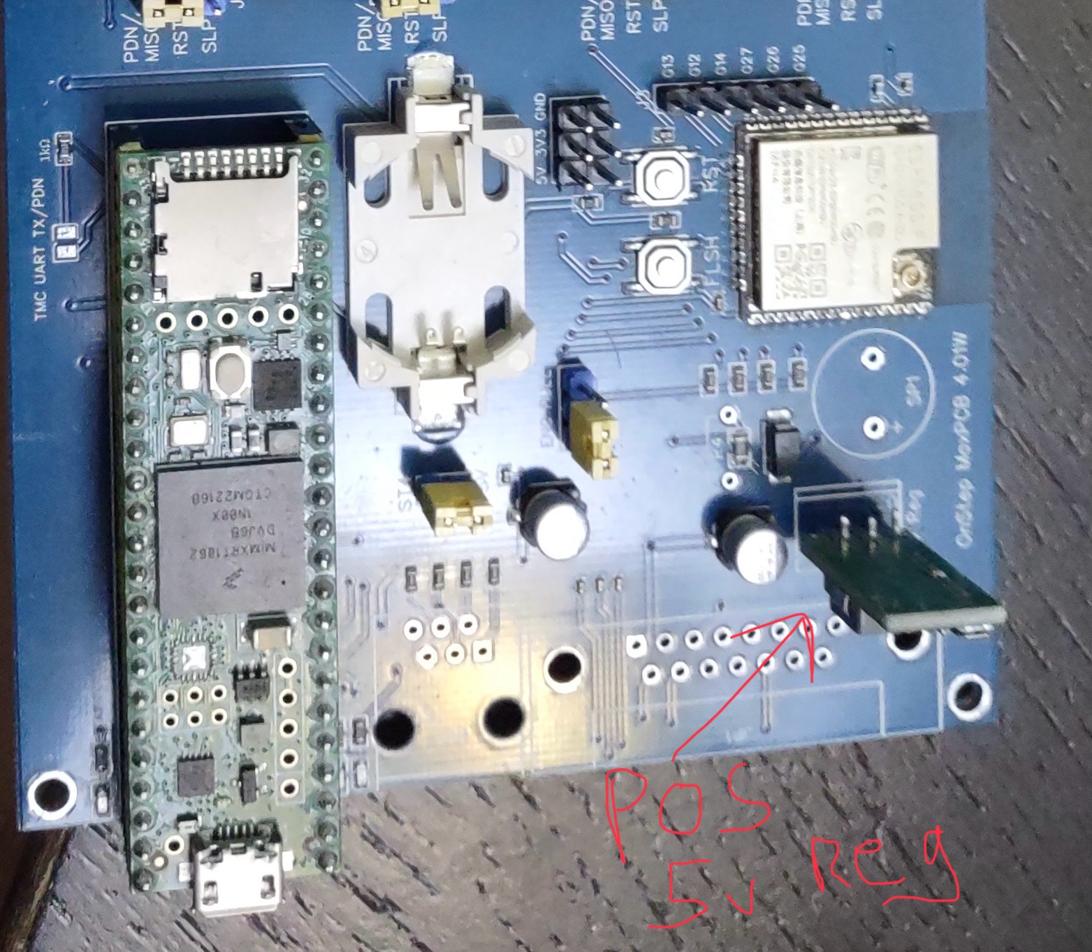
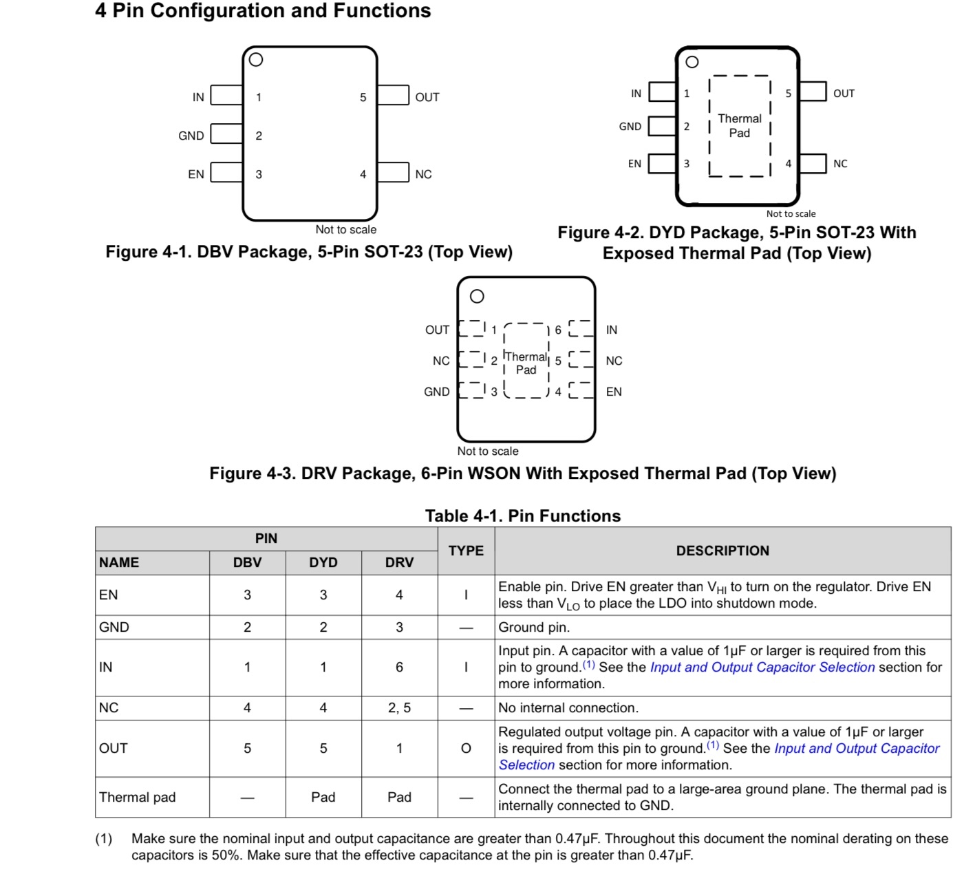
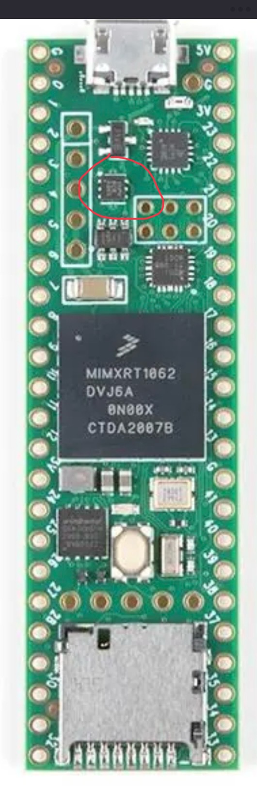
I have a project that is using a Teensy 4.1, the cheep 5v regulator I was using in the project let the magic smoke out for no good reason. I replaced that but now the Teensy boots and runs for about a min then quits. There is a TLV75733P power IC that is supplying the 3v3 and it gets hot then quits supplying power. Since that IC is $0.46 vs a new Teensy 4.1 ~ $40 I want to try and replace it. I have done a bit of SMD work but not tried to remove a tiny chip with a GND pad before so I’m looking for any tips. The PCB of the Teensy has header pins so I can’t really get good contact to a hot plate to preheat the board.

59
1
submitted 10 months ago* (last edited 10 months ago) by [email protected] to c/[email protected]


I am working on a WLED project, using a esp32 in a 3d printed enclosere. But my dad says that i can't install it because it is not UL listed. He is worried if the house burns down, the insurance company won't insure it due to diy electronics possibly starting a fire. What am i to do, i am not developing a project to sell?

60


Hello !

I recently 3dprinted a train whistle that usually works with a mouthpiece. It works by simply blowing air in it.

However, I would like to convert it to a whistle for my bike. For that I would need a system that could blow air in it, instead of myself, with the press of a button.

Any idea on what i could start with to build that ? It would be best if the circuitry was quite compact too.

Thanks !

61


I want to store a battery powered device long term (decades) as a reference article, it will never be switched on or charged again. The problem is that it contains a small LiPo battery that will be very hard to remove.

Is there likely to be any significant risk I need to worry about? Once depleted will the battery be relatively inert?

62


EDIT: Thanks everyone for you help, that has been very instructive. I think I just have a very poor quality cable adapter. Given that Blueretro is mostly an opensource DIY project, I’ll make a cable adapter myself instead of trying to fix what would obviously not function properly.

Hi everyone,

First of all let me say that I’m a total noob in electronics (I really only know the basics) and I’m facing an issue that I really don’t know how to tackle.

I have bought a Blueretro NES adapter on Aliexpress (this one) and it does behave erratically when powered by the console alone (Bluetooth not working, LED indicator down, random outputs to the console).

When I’m powering via USB, everything function properly.

So I guessed that I might have a voltage issue on the NES side. I tested mine and make a few friend test theirs (5 in total including mine) and the result is still the same: the controller ports outputs between 4.6 and 4.8V instead of 5V.

The Blueretro itself apparently uses an AMS1117 (picture here) which, from my understanding, is stepping down 5V to 3.3V (wild guess, I don’t really know what it does, just quickly read the datasheet).

So, sorry for the long intro, here are my questions:

  • Is it wise to try to step up the voltage from the NES to the Blueretro from 4.6V to 5V? How would it be possible? Is it even possible?
  • Given that the Blueretro is taking 3.3V apparently, is it possible to step down from 4.6V to 3.3V instead? Is it wiser than stepping up?

Thanks in advance and sorry for the long post :)

63


So my wife cracked the screen of her Playdate console. I got a replacement memory LCD (Sharp LS027B7DH01A), but the LCD is mounted with optically clear adhesive directly to a piece of glass which is adhered around the edges to the console’s faceplate.

The glass measures 65.15x41.64mm by 0.65mm thick. Definitely not a standard size. I can’t find anywhere to buy glass so thin and so large.

My first thought was to cut a phone screen protector down to size with a glass cutter. My first attempt failed because the screen protector I bought was actually coated in plastic on both sides. Even if I got a straight cut, I couldn’t find a way to slice through the plastic layers cleanly.

Any ideas on where to find cuttable glass sheets this thin? I could try more screen protectors, but there’s no way to know if they’ll work before buying them.

64


I came across this today and I thought it might be an incredibly powerful tool. So I was curious to see if anybody in this community has used it yet?

65


I'm new to electronics and looking to assemble an array of components and tools for working on and designing electronics & circuits. Something immediately apparent is that all of the widely available kits orient you towards working with microcontrollers and SBCs; these kits are cool, but I want to have a halfway decent understanding of the underlying analog components and circuit design before I go digital.

With that in mind, what should I get? If anyone could specify specifics to look into, I'd really appreciate that! Thanks for the help.

Current list

  • A decent breadboard
  • Jumper wires
  • Multimeter
  • Batteries
  • Variable Power Supply?
  • Assorted resistors (1Ω-?)
  • Capacitors (Electrolytic and ceramic?)
  • Various ICs?
  • Transistors?
  • Diodes, probably?
  • Potentiometers
66


Hi everyone

I've been experimenting with methods of applying etch resist with a laser and dry film. The process is kind of arduous and error prone.

Developing with sodium carbonate solution to clear unexposed etch resist takes long, doesn't work well and if you leave it too long the developed etch resist will break as well.

I use a laser module attached to a 3D printer to draw the PCB (LCB?) on the etch resist. This laser almost instantly solidifies toner for laserprinters and also almost instantly hardens dry film.

Using powdered toner and a laser would be a much quicker way to apply etch resist since the excess can be wiped off and reused easily. The problem is applying a uniform layer of toner.

Suspending toner on the surface of water and hydrodipping the plate seems to work but drying takes too long.

Spray coating could work but is messy.

Isopropyl alcohol softens the toner too much making it impossible to clean the excess off.

I have not tried using a roller or electrostatic application yet but that could work well.

Does any of you have experience with this and have ideas/advice?

67


So, I've got a laptop screen that's giving up on me. 2/3 of the screen runs alright but the 1/3 on the left edge is acting weird. Half of the broken section displays an image but the image smudged and weird, while the other half is just dead. I opened it up to see what's up and, lo and behold, a wee tiny capacitor is missing (I know it's a capacitor 'cause I looked of the board marking, C248).

Now I'm wondering, since ordering a single capacitor just for fixing this screen is not worth the effort, can I just... put some solder in there to at least get power to where it needs to go? I know it's definitely not ideal but, this is an ancient laptop. Putting in the effort to fix it perfectly is not exactly a great value proposition. What I want to know most is, will the screen be damaged if I do this, or what could go wrong if I do this?

I'm pretty new to DIY electronics fixing so sorry if this is a stupid question. Thanks in advance y'all. Cheers!

68
 
 
69


Hey guys i cant find any usefull guide on how USB c charging works in depth. In particular i have bought a pair of Sony headphones which i would like to make wireless change so I also bought a crappy wireless coil meant to convert a phone into wireless charging. i opened the headphones, located the ground and 5v pin coming from the USB connected the circuit and surprise the charging led doesn't light ... The charging board is separated from the main board so I checked the flat cable that connects them, found the 5v and gnd ,spliced into it, and the led light lit as if it was charging. the next morning the led was of signaling the headphones are full, unfortunately after powering them on the battery status indicated was still 20% as the evening before ... Have I done anything wrong ? What about that phase when they negotiate the power output with a magic resistor ? What should I try next? Thanks in advance 👍🏻

70
 
 
71
1
submitted 1 year ago* (last edited 1 year ago) by [email protected] to c/[email protected]


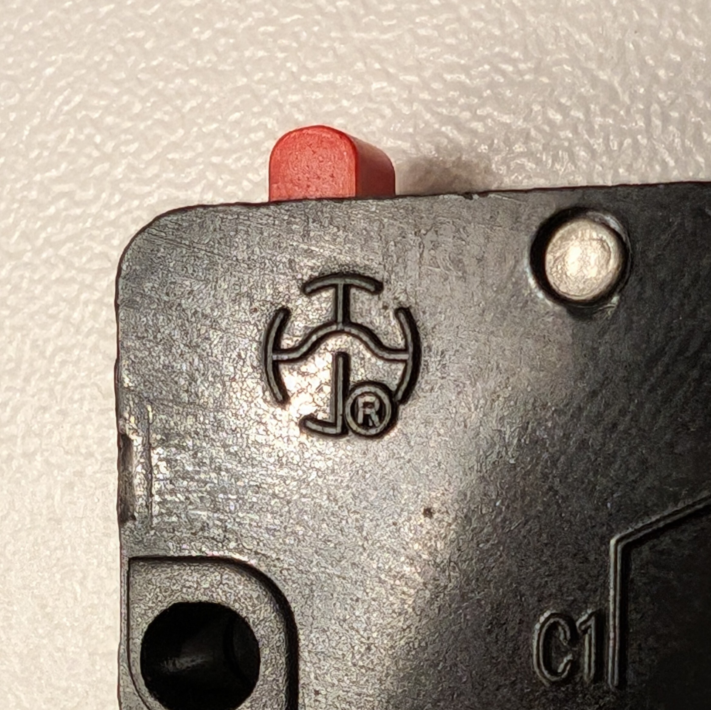
It's an SPST-NO micro switch. Don't waste time searching for it. I already wasted mine. Just let me know what it is if you know it off the top of your head. 😊

72


I'm an EE by trade focusing on embedded devices, but most of my work is in relatively low-power STM32 applications. When I stopped following developments in hobby kits, it was mostly Arduino Unos slowly driving I2C OLED displays.

Now suddenly, there are embedded Raspberry Pis and ESP32s doing realtime facial recognition and video feeds.

Is there a good place to look to catch up on what's now possible with these embedded devices?

Also, while I enjoy the ease of the hobby kits, I'm also interested in more mass-production-focused solutions.

73
0
submitted 2 years ago* (last edited 2 years ago) by [email protected] to c/[email protected]


Hey folks, I have a Mackie 802-VLZ4 mixer which does this narsty pop when you turn it on; I'm pretty sure it's what killed one of the woofers in my monitors. It has been put out of service and I will either harvest its many through-hole organs or else fix it.

I could not find a schematic, but I don't assume it can't be found, I just haven't yet. It's not a big board but it's all analog from what I can see.

There appears to be a separate power supply board which feeds

+15 AGND -15 GND +48

to the mixer, which is two boards connected by thick soldered wires.

I have looked with magnifiers on at all the caps, none appear to be leaky or swole, but I'm assuming this has something to do with the power supply putting out a spike at power on. The power board has a lot of really tiny caps, I still don't really understand power supplies that well. I need to do more studying of them I suppose, they're pretty central.

Edit: I have a little tiny oscilloscope that I bought years ago and haven't used yet, just figured the day would come. This is probably that day, to measure that spike from the power supply. From the looks of it I'm pretty sure that if I can just get better quality, non-spiking power to those connectors it should be fine.

Anyways this board would be very handy right this second if I felt like it was safe to let it touch my good kids, but at the moment it's the unfavored child who won't stop hitting the others. If anyone would like to see them I have/can take photos. The boards have codes on them, presumably codes that Mackie employees could use to dig up schematics, but will they? I suppose I'll try to find out today. It's past warranty of course.

74


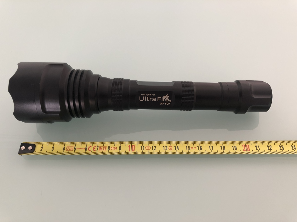
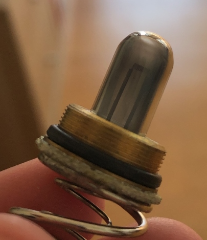
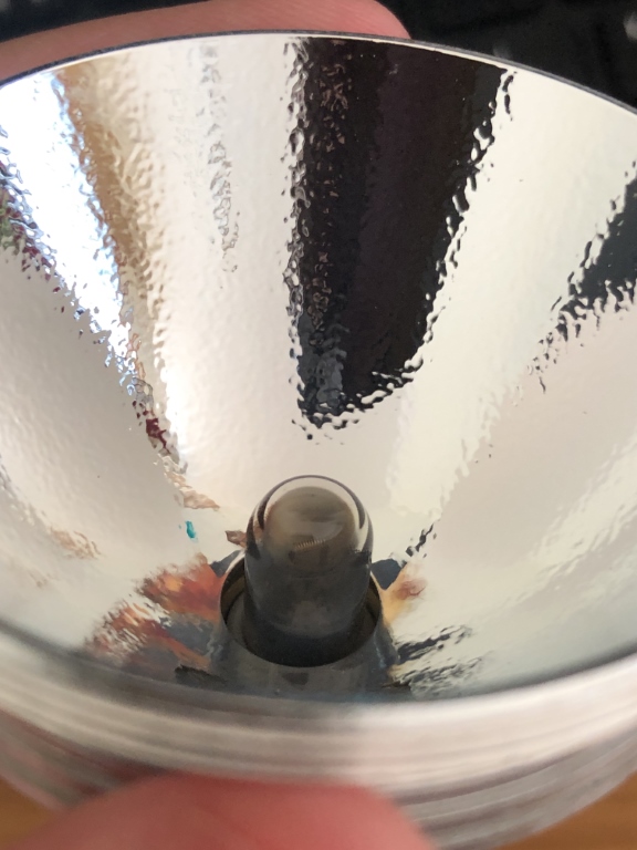
Some years ago, before LEDs were a thing, I bought an Ultrafire WF-500 Flashlight that features a Xeon light bulb. As you might imagine the bulb reached its lifetime and burned away.

Now a replacement bulb is available here https://www.ebay.com/itm/321916301663 the thing is that it will cost me 35€ and for that price I could just buy a new LED flashlight.

Now I was considering trying to adapt a generic LED bulb like this one here https://www.aliexpress.com/item/1005002419159094.html?mp=1.

Anyone else with this model of flashlight succeed at a similar mod? Any LED bulb recommendations? Or... is there any other source for the original bulb at a lower cost?

Some photos:

Thank you.

75


Serious question from a beginner in electronics. For reasons I do not fully understand, I have become fixated on the idea of collecting small amounts of electricity from “interesting” sources. I don’t mean “free energy”, instead, I mean things like extracting a few mV from being so close to a AM radio tower using two tuned loop antennas in phase with each other, or getting a few mV from the rain’s kinetic energy with PTFE and using two electrodes which are shorted when a drop of rain hits it. In short, I’ve done small experiments to confirm that I can get a few mV and enough to get me excited but not much more. I know I’m not going to get much power out of this, but I’ve been able to charge a NiMH battery a few mV by being a quarter mile from an AM radio station with my antenna setup. It would be fascinating to me if I could store these small charges in something like a 5V USB power brick eventually.

The smarter idea would be for me to harvest energy with the sun or from the wind or a stream. I’m tinkering with this as well, but larger amounts of electricity scare me for right now. I guess I’ve seen enough experimental sources of harvesting electricity and I’ve gotten the itch to invent, which is a dangerous itch for a newbie like me to have.

The best advice I’ve seen online (ok, it was ChatGPT) is that it’s just not worth it to work with such small amounts of electricity, because the equipment required is too expensive and sophisticated (e.g, devices to read the charge of a capacitor without discharging it) to make anything that’s efficient enough to be worthwhile. Would you agree? Do you know of some other fascinating source of gathering electricity that I should also waste lots of time on?

I just have all these electronic components and magnets and when I move them together the numbers on multimeter get bigger. it’s neat.

view more: ‹ prev next ›